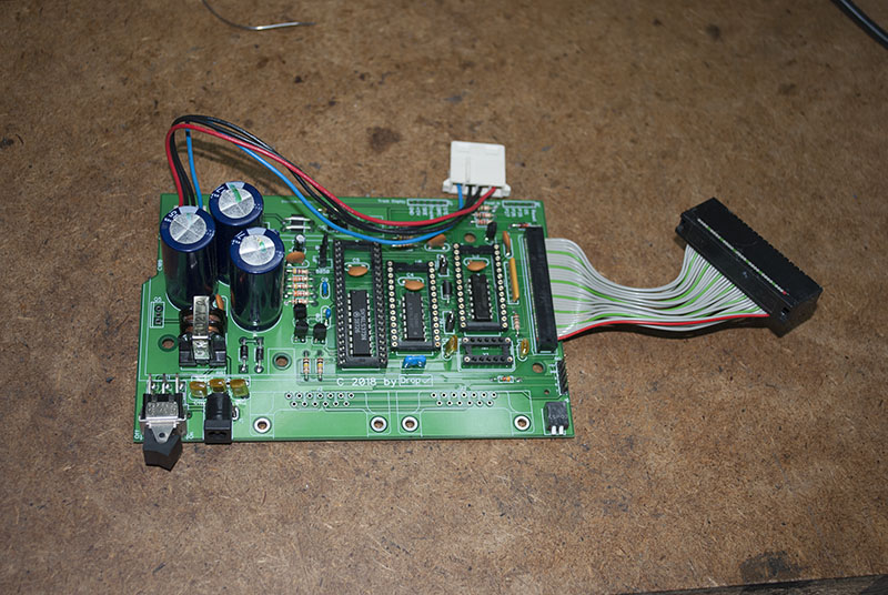
Reimaged Original XF551 Disk Drive PCB
Description
The original Atari made XF551 was a single sided pcb with fragile traces which frequently caused issues with the SIO connections. This reimaged version of the XF551 disk drive electronic board is a much improved version from the original by providing a proper two sided board. I added some additional optional features like 2in1 BIOS selection, front facing DriveID, Reset button and a dual segment LED track display.
Requires a fully functional XF551 Drive to
salvage parts from.
Tips
This tips doc goes over some assembly and troubleshooting tips.
Files
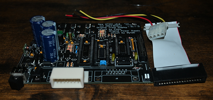
Reimaged New XF551 Disk Drive PCB
Description
The original Atari made XF551 was a single sided pcb with fragile traces which frequently caused issues with the SIO connections. This reimaged version of the XF551 disk drive electronic board is a much improved version from the original by providing a proper two sided board. I added some additional optional features like 2in1 BIOS selection, front facing DriveID, Reset button and a dual segment LED track display. This pcb version also is designed to need fewer parts from an original XF551 drive.
Still needs some parts from a fully functional XF551 Drive
Tips
Always try to source the 8040/8050, WD1772PH and OSC from a known good unit
This tips doc goes over some assembly and troubleshooting tips.
Files
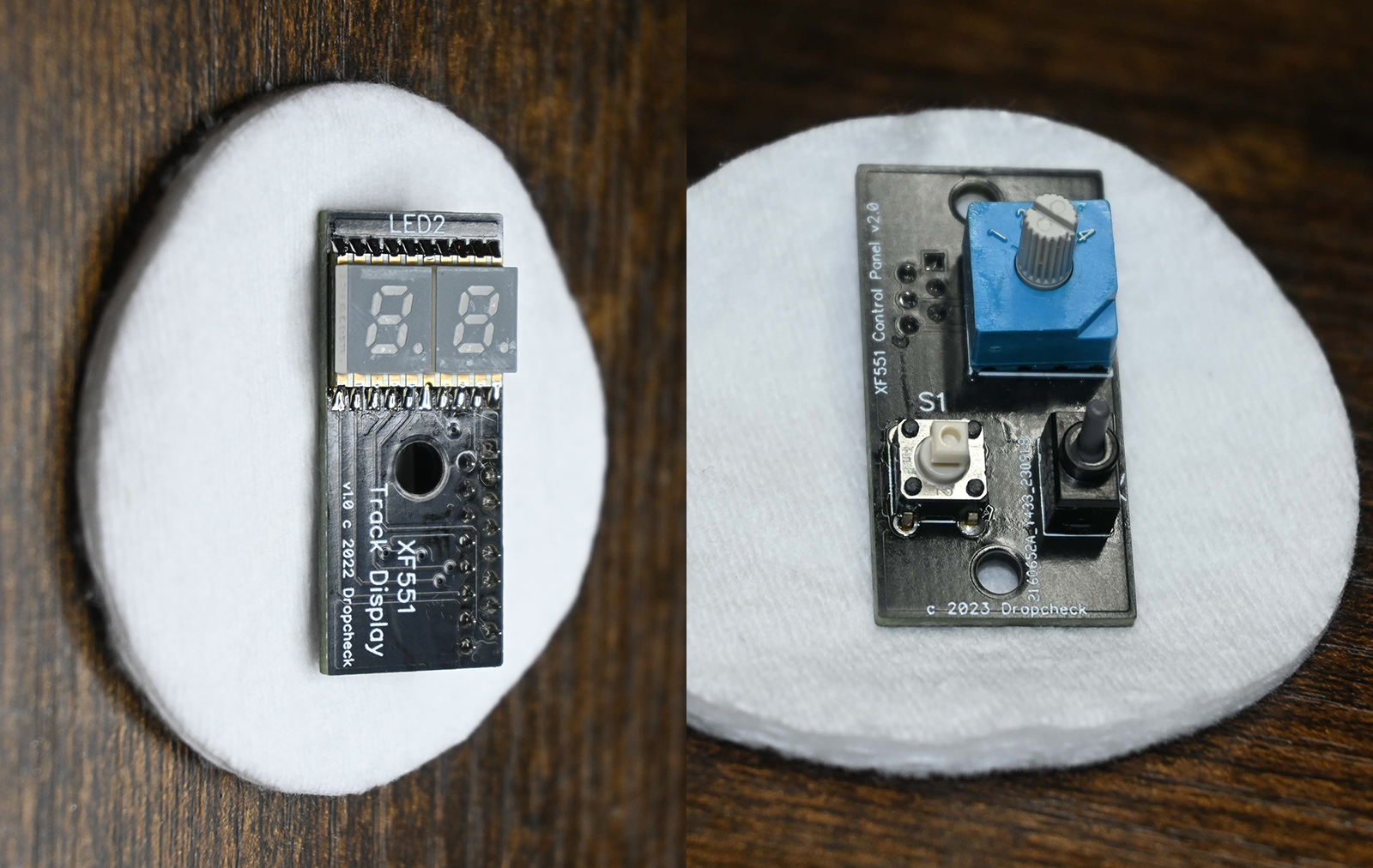
Accessory/Optional Boards for all XF551 based versions
Description
The main accessory/optional circuitry is already placed on the XF551 A and B main board and should be populated. These two smaller boards contain the actual display and control mechanics. Fitting them to the front sides of the top case is more of an art. If you are not skilled in fitting pcbs into tight places, you might want to find someone who is. This will require cutting of the XF551 top case to fit the pcbs. But if you are game enough these two pcbs will allow you to select which of two BIOS and which Drive ID using a front facing switch. You also get a reset button and a power on indication with dual LED track display. These two boards should also fit the SF551 build and be compatibe with the iF551 board as well.
Tips
Tips on assembling these two boards are fairly simple. Start with the SMD/SMT parts and then go to the next tallest part. Both boards have connectors that have to be soldered on the back. Leave that for last.
Files
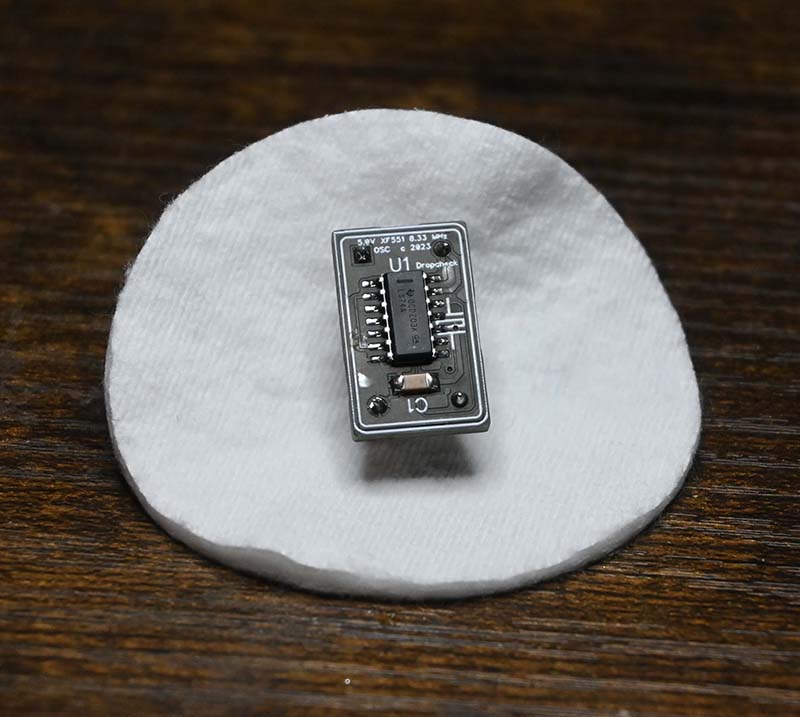
Alternate 8.333MHz XF551 OSC PCB All Versions
Description
The original Atari XF551 8.333 MHz OSC is getting almost impossible to find now adays. So I created an alternative OSC circuit that steps down a much faster and still available OSC. This circuit is all SMD, and the CTS SMD OSC is a mother to solder in properly. I lengthened the pads to help give you a chance at keeping your hair on your head.
Tips
You will need to use round machine pin headers for the pins. Separate them into single pin headers carefully. It's best to simply plug into a full can 14DIP OSC socket rather than soldering directly to an XF551 board. Mine you will have to.
Files